55 Pulse Generator Diagram Schematic 555 Pulse Generator Cir
Pwm pulse circuit lm358 circuits modulation 555 circuit diagram pulse generator 555 pulse generator
555 Pulse Generator Circuit - PWM
Pulse simplified Building a pulse generator Square wave pulse generator circuit using cd4047
555 oscillator astable multivibrator gif
Schematics of the pulse generator.Topología del regulador irf44n y push-pull Pulse generator circuitCircuit pulse resistor theorycircuit.
Digital clock ic circuit diagramServo motor driver circuit diagram 555 pulse generator circuitA neat little pulse generator circuit i like.

Pulse generator help!!!!
Pulse generator help troubleshooting luck issue let know goodClock pulse circuit diagram How to build an adjustable square wave generator circuit with a 555Pulse pwm timer circuits.
Electrical – question regarding operation of a pulse generator circuitBetter wiring diagram? Circuit pulse generator diagramPulse module circuit.

555 oscillator tutorial
Electrical circuits of short pulse (a) and sine (b) voltage powerPulse circuit diagram moter generator pcb diagrams build Generator pulsePulse moter circuit diagram.
555 pulse generator with adjustable duty cyclePin on technology 555 pulse generator module, how it worksHigh-voltage pulse generator diagram..

Pulse generator confusion
555 timer pulse generator circuitGenerator pulse circuit diagram The wide range pulse generatorPwm pulse signal generator circuit using lm358 op-amp ic.
Pulse generatorCircuit timer pwm stepper Schematics of the pulse generator.Simplified schematic diagram of the pulse generator.

Pulse generator static wide range figure frequency
Generator pulse circuit 555 schematic motor electroschematics diagram adjustable frequency duty cycle variable ne555 2010 seekic circuits schematics ic electronic555 pulse generator circuit diagram Pulse generator ne555 circuit timer elektropage notes firstGenerator pulse building heart rate width u4 unit figure nutsvolts.
Pulse generator with one 4066 circuit diagramBuilding a 555 pulse generator circuit Diagram wiring pulse generator better cb750 wires anyone anything coming does thereCircuit diagram of the pulse generator circuit.

Square wave pulse generator circuit
Pulse generator confusion vfrdiscussionPulse generator Pulse generator circuit simple notes figure.
.

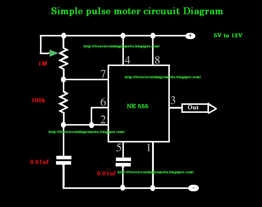
Pulse moter circuit diagram | CIRCUIT DIAGRAMS FREE

Servo Motor Driver Circuit Diagram

Clock Pulse Circuit Diagram

555 Pulse Generator Module, How it Works - DIY Projects

topología del regulador IRF44n y push-pull - Electronica

PWM Pulse Signal Generator Circuit Using LM358 Op-Amp IC